The beginning of May was time to start thinking about setting a date for the big rolling event....the logistics involved....and the amount of time needed to get ready for the day. It seemed that completing the rear deadwood and glassing the hull seemed to be the only projects left. But then, there was the design and build of the rolling cradle, the need for a new lower strongback on wheels and even the building of the blank for casting the lead keel.
The rear deadwood was laminated up and held in place with silica bronze ring shank nails while the epoxy was drying. There was no place to get grip for clamping, and each piece needed to be layered on the one below it since there would be no secure way to attach a preformed deadwood on to the hull.

A string nailed to the hull and draped over a temporary frame helped lay out the angle of the rear cutout that will ultimately accommodate the propeller.

New angles were determined and layed-out as the laminating continued.

The sides were still very rough.

Then the shaping begins.....

Thank goodness for power planes.


Shaping the back end of the deadwood reveals the edges of some of the bronze nails used in the laminating. These will not rust and will be covered with glass, thus they can be left in place.

Lots of measuring and fairing the right and left side by using the short level and lots of eyeballing.

Looking pretty nice...

And of course, right on the offset numbers....Cabinet makers building boats!.....


This provides a good visualization of the final keel shape...I am getting excited.

Plywood that would be thick enough to provide structure to the blank could not be bent enough to make a smooth curve, so some "junk wood" strip planking was applied to create the actual shape of the sides.

A particle board form was placed to make the cutout for the centerboard.

Looking beautiful, and equal...

The area of the deadwood that jogs in will ultimately be drilled for the prop. The rudder is designed to lay down the angle of the transom and attach to the jutting portion of the deadwood.
That is one big solid piece of wood!

The blank for the lead ballast can now be removed from the hull and finished up.
The centerboard slot is visible, as well as the slight curve to the sides.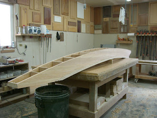
The length of the blank is 15-16, and it is maintaining its shape well.
A little well deserved break during the picture taking....
Read More..
The rear deadwood was laminated up and held in place with silica bronze ring shank nails while the epoxy was drying. There was no place to get grip for clamping, and each piece needed to be layered on the one below it since there would be no secure way to attach a preformed deadwood on to the hull.
A string nailed to the hull and draped over a temporary frame helped lay out the angle of the rear cutout that will ultimately accommodate the propeller.
New angles were determined and layed-out as the laminating continued.
The sides were still very rough.
Then the shaping begins.....
Thank goodness for power planes.
A little scaffolding helps with the job of needing to go from one side to the other and back again...a little shaped here and a little shaped there....

The front and rear angles are measured and trimmed to the drawings.
The front and rear angles are measured and trimmed to the drawings.
Shaping the back end of the deadwood reveals the edges of some of the bronze nails used in the laminating. These will not rust and will be covered with glass, thus they can be left in place.
Lots of measuring and fairing the right and left side by using the short level and lots of eyeballing.
Looking pretty nice...
And of course, right on the offset numbers....Cabinet makers building boats!.....
The next project was to build a blank to use in creating a form to cast the lead keel. The shoal draft lead ballast is shaped so that there is no flat aspect to it (sides, top, or bottom) and needs the cutout for the centerboard. After creating and fairing the blank, Richard is contemplating creating a mold from concrete for the foundry to pour into....more research will need to be done for the logistics of this....but creating the blank at this stage is much simpler than trying to form one to the hull shape after the roll.

Several layers of 1/4" plywood were laminated along the top curve of the hull as a base for the blank.
Several layers of 1/4" plywood were laminated along the top curve of the hull as a base for the blank.
Little center supports were cut to size (for the offset numbers) and mounted to the base along the ridge of the hull.
This provides a good visualization of the final keel shape...I am getting excited.
Plywood that would be thick enough to provide structure to the blank could not be bent enough to make a smooth curve, so some "junk wood" strip planking was applied to create the actual shape of the sides.
A particle board form was placed to make the cutout for the centerboard.
Looking beautiful, and equal...
The area of the deadwood that jogs in will ultimately be drilled for the prop. The rudder is designed to lay down the angle of the transom and attach to the jutting portion of the deadwood.
That is one big solid piece of wood!
The blank for the lead ballast can now be removed from the hull and finished up.
The centerboard slot is visible, as well as the slight curve to the sides.
The length of the blank is 15-16, and it is maintaining its shape well.
A little well deserved break during the picture taking....


