Tampilkan postingan dengan label planking. Tampilkan semua postingan

The Planking Begins

| 0 komentar |
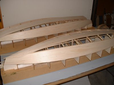
After all the fairing required to make the entire hull flow nicely, there were a few more things to take care of prior to the beginning of planking. We had to deal with things that would be inaccessible after the planking was applied. Anything that could be anticipated and easily placed prior to planking removes the need to try and shape things to fit against the inside curve of the hull at a later time.


The appropriately sized diesel engine was chosen, and the appropriately sized engine mounts were built.


The mounts consist of two skid type mounts sitting above the bottom of the bilge.


The picture below shows how the centerboard case sits in relation to the bulkhead that forms the back of the galley sink cabinet.


The entire interior of the aft lazarette needed to be fiberglassed and epoxied, and the final sanding done to smooth it out, ready for paint. Once the planking is applied, this area will only have a small access hole, not something a person wants to have to manipulate fiberglass and sanders through.


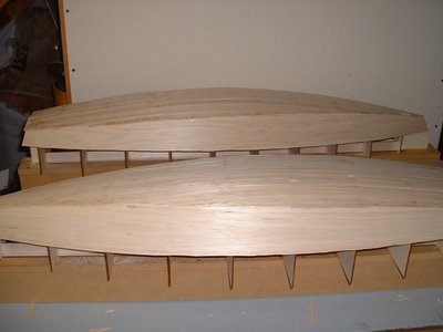
Finally the planking could begin....Richard ordered some beautiful 1 x 6 clear vertical grain Western Red Cedar from Specialty Forest Products in Spokane, WA. It is light weight and rot resistant, and thus is desirable for use in wooden boats. The cost of this special lumber was offset by the fact that the waste factor disappeared by ordering it clear and not having to cut around knots, etc as would be the case in a lesser grade or knottier wood.

He ripped it to 1 1/16" width and planed to 3/4" thickness (the dimension from inside to outside of hull). The width of the strips was recommended at 3/4"-1 1/2". It is necessary to keep the strips narrow enough to be able to run each layer of planking the entire length of the boat and have it bend as needed to follow the lines of the hull. The joints are staggered with each layer and epoxy applied to the joint ends.


Epoxy was spread on each long strip and then applied to hull, starting at the sheer.


Massive numbers of clamps were used. Thanks to cheap clamps from Harbor Freight!


Richard decided to start at the sheer, and to work from bottom up exclusively. The theory behind this was that he would never have to be applying epoxy to the underside of any surfaces and working upside down. The hope was that the strips would flow nicely all the way up the hull since it was faired in all directions.


Smear, clamp....


Smear, clamp, repeat....

Still not much room to get around the hull, especially with all the clamps in place.


Notice also that the opening into the building room from the garage at the bow has been widened and heightened to help with access and ultimate boat removal. It will soon be drywalled and taped, and hopefully it will be the last bit of renovation needed for boat removal.


It still doesnt look like it will fit from this angle! But tapes dont lie, right?


After laying several rows, Richard waits for the epoxy to begin setting, then scrapes the gross excess to avoid a killer sanding job later.

A hand sized piece of laminate works great for this scraping.

Another fancy addition to the tools was the OMER nail gun that shoots plastic nails from Raptor. The beige plastic nails hold the strips in place while the epoxy dries. The use of any metal nails, other than bronze, would result in the nails rotting and weakening the hull, or needing to be removed. The price of a gun that only shoots plastic nails was cheaper than numerous boxes of expensive silicon bronze ring-shank nails and the shipping costs required to get them here. Not to mention the labor to sink all those nails.


The planking picked up speed as the learning curve was smoothed out.

Read More..

Lapstrake Planking cutting a rolling bevel

| 0 komentar |
I recently received an email from Patricia Hong, asking for some clarification on the system I use for cutting plank bevels when building lapstrake (clinker).  I thought the email and my reply (attached to the original in red to save time - we were still in flood-recovery mode) might be of interest to others. Here it is, along with some illustrations for clarity.

?
?
That is me, cutting a plank bevel on the first Periwinkle
? ? 1 :  Is this plane just drilled and a threaded rod put through the body of the plane ? I just drilled one of my low-angle block planes (on a cheap drill press) to accept a piece of brass rod which I had on hand. The rod is a neat fit in the hole, and can slide through to project any length I want, on either side of the plane.

2 :  Does the rod align flat  with the bottom / bed of the plane ? The bottom of the hole (and the bottom of the rod) are 11mm above the bed of the plane. I did this because I had access to cheap pine square-section moldings from the local hardware store which were 11mm x 11mm, and I used these as battens. See answer to next question. 

3 :  The guide / rod appears to be riding on the batten fixed to the mold stations and frames/bulkheads to  follow the rolling bevel of the laps .
Does this batten have to match the thickness of the planking stock in order to cut the correct bevel on the planking stock ?
No, it is independant of the planking thickness, but the batten needs to be the same thickness as the distance from the bed (or sole) of the plane up to the bottom of the rod (or the hole). So if a tangent to the rod was positioned 12mm above the sole of the plane, you would need to use a 12mm batten, and so on. All that you are doing is ensuring that the sole of the plane is parallel with an imaginary line drawn from the point where the next plank touches the mold (i.e. where the batten is positioned - in fact parallel with the bottom surface of the batten) to the bevelled lap on the plank which is already in position. I think my description is confusing, but the attached sketch may explain.


I hope you don`t mind all the questions No, I dont mind at all, and Im only too happy to help where I can , and I hope they make sense to you Yes they do, and I think they are very sensible questions , as  I would really try my hand at clinker / (  lapstrake? )  boat building , and your method of cutting rolling bevels appears to be the best way to do this. Glued lapstrake is my favourite method of construction for small craft. It is nowhere near as difficult as some people imagine, but it does need the application of some common sense. Please let me know if you want more information. There are several excellent books on the subject,including Iain Oughtreds "Clinker Plywood Boatbuilding Manual" , Tom Hills "Ultalight Boatbuilding" and "How to Build Glued Laptrake Wooden Boats"  by John Brooks and Ruth Anne Hill.
Read More..

Star 45 Construction Planking with edge glueing

| 0 komentar |
[Star45] Update on planking bottom with edge glueing.

John Fisher is ready { 4/19/2007 } to glass his latest boat and is sharing how he planked it. His dad built a ply sided, cedar planked star using titebond II and it came out pretty light and stiff. With this information I started to build another hull using the same materials. He felt that edge gluing the planks added a lot of the strength to his boat. John didnt want to glue in extra wood to hold the pins to keep the planks in place for the glue to dry, so I combined two methods of planking. John liked the quickness of planking with CA and kicker, but it lacked stiffness when sanding the bottom before glassing. So he decided to edge glue the planks and then tack them in place to the frames with CA.

In this photo you can see where John put drops of CA on the planks. The wood is slightly darker.


It worked well. John has an edge glued bottom and he was able to plank it in one evening. To do this John first spray the frames with kicker, then apply titebond III to the edge of the planks. He then would hold the plank in place, tight against the previous plank, and apply a drop of CA to each frame to hold it in place. It did not matter where John started, bow, stern, or middle, but do make sure the CA has set up before moving to the next frame. Once the whole plank was in place he came back and wiped off the extra titebond. To fair the bottom to the sides he used a $10, 6" plane from home depot set at .010" depth of cut. It quickly removed the cedar and a little sanding finished the job.

John had one plank that was too thin that he had to remove, it was harder than expected. He had the use quite a bit of force to break the glue joint at each frame, so he is confident that this method is strong. John will also use this for balsa planked bottoms.

In photo # 10 you can see the stern still needs to be trimmed and sanded. John will probably use a saw to trim in close and then sand to fair it.
Read More..

Sailing Model AMYA Star45 Class Planking bottom of hull

| 0 komentar |
From John Fisher:

Photograph by John Fisher


Photograph by John Fisher


Since it was requested here are a couple of photos of planking the
bottom of my two wood/glass stars. photo 01 is the bottom of the first
star about half way done. Planks are 1/16 X 3/8 balsa. These were cut
from a 48" long sheet. Weigh your balsa before buying it. I would not
use a 3 X 48 sheet that weighed in at more than 22g. It takes 3 sheets
to cover the bottom and you could add another 1 to 1.5 oz by using
heavy balsa.

I started in the middle and worked to the outside. I sprayed the
shadows with kicker, then put down a plank, then added super fast CA to
hold it down. If the kicker was not dry enough it would cure before it
wicked into the joint which would cause the next plank to not fit
correctly. I had some variation in the planks, but once they were
glassed the bottom smoothed out quite a bit.

If I were to do another one I would add the half frames. I will be
adding them to the DXF files in the next couple of days for anyone
wishing to cut a set.

Picture shows the bottom after it was completely planked. On the
second boat I got a nice pattern on the bottom since the balsa sheets
had different grain structure. I sanded the sided flush and got the
bottom relatively smooth, but not perfect. With the balsa planks they
were flexible and if sanded too much you get thin spots at the frames.
The glass smoothed out inperfections. If doing a hard wood bottom the
planks should fit better than what I did with the balsa.

John Fisher 2006 August 15

Read More..

Planking the Deblois Street Dory

| 0 komentar |

Deblois Street Dory Building

Bar Harbor, Maine

Planking the hull


I spent the last 24 hours in Bar Harbor helping a customer get the planking going on his DSD. He has been pining after his own D Street Dory for a few years and is very excited about his project. We met at the Small Reach Regatta, where he and his wife row and sail their current stitch-and-glue dory. He wanted to build a real dory and one with more performance and capacity than the others available. He chose the DSD!

Hull #1 built in 2007, on the shores of the Maine Coast


He set up the strongback very accurately, scarphed planks, and got everything ready for my visit. I arrived at 11am and after the 10-cent tour of his new, beautiful, custom house perched on the edge of Acadia National Park, we got to work. By 8pm we had the garboards fit and glued and looking perfect. Pretty good time for 2 people going hard at it and taking a lunch and dinner break, too. Garboards are often a two-day project because they can be the trickiest to fit.

The latest mkII version of the DSD under construction on MDI

The DSD kit is available, just give a call at 207.602-9587 or email boatkits@gmail.com


Read More..

More About Fine Lines and Lapstrake Planking

| 0 komentar |
Dennis has written a comment about my last posting which is quite interesting: -

Ross, this is precisely the problem I face in my own region sailing in the Great Lakes USA. The water never gets warm, really, and getting a dousing is not a lot of fun, especially as one ages and gets "thin blood." Your first picture illustrates perfectly the trouble my 15 ft sailboat gives me. And while she sails very well, I increasingly feel the need to replace her with a drier boat.

I figured the problem was that there was not enough flare in the top sides of my boats fwd section. Does flare contribute to a fine entry? The relationship between the two is not clear to me and the picture of Phoenix III seems to challenge that supposition. Can one have a beamier boat than the Phoenix III, say 6 ft, on a 15-15.5 ft length and still attain a fine entry to the bow you mention in your blog?

Best, Dennis


Well, this is a very good selection of questions, and the answer to all is, "Yes and No".

Yes, flare can contribute to a fine entry angle at the waterline and below, but it is only one of the design elements involved. To get a combination of flare, adequate breadth (or beam, as it is commonly called), and fine entry angles, you usually need to have a construction method which allows for compound curves in the structure. I will describe an exception shortly, but compound curves normally eliminate sheet material (for us that means plywood) as a building material.

The forward sections of Phil Bolgers Harbinger design
In the above photo, you can see a hull which is very wide (7 1" on a 15 LOA) and yet has extremely fine entry lines and substantial flare.This boat was designed to be built using bent-frame carvel planking - a system which allows one to build a hull which contains compound curvature. Other options would be strip planking, cold molded using muliple layers of diagonal veneer, or, as I did with this boat, strip/diagonal, which is a combination of stip planking and double diagonal.

There are other options. Take as an example this lobster boat - also a Phil Bolger design, which I built using glued-lapstrake planking.

Planty of flare, but lots of planks

Phil Bolger Hope showing her fine lines

Once again, there is plenty of flare and a fine entry angle - all in a boat which is wide for her length. In this case I was only able to achieve the required shape by using a lot of narrow planks. In therory, if I had used an infinite number of planks, I could have achieved any shape I wanted, but the building process would by infinitely time-consuming and infinitely heavy - so a compromise had to be reached.

When I was designing Phoeinx III and Periwinkle, I was determined to use the minimum number of planks which was consistent with an nice hull shape. This allowed me to capitalise on the wide planks which could be cut from standard sheets of plywood, while at the same time reducing the marking, cutting, and gluing labour time for the builder. Once again a compromise. The individual planks were wide enough to need to be developable shapes, but I still had more latitude with hull shape than would be the case with a sheet plywood boat.

The first Periwinkle awaiting her launching
 One of the design elements which allowed me to get a nice shape with so few planks was that the boats were relatively slender for their length. There are other good examples in the work of Joel White and Iain Oughtred and others.

Periwinkle, showing that she is relatively long and narrow.
There is another option, and that is to take sheet plywood construction to the limits of plywoods ability to twist and bend at the same time. This approach requires very careful design to ensure that all planks (or hull panels in this case) are what is called "developable". What this means is that the hull shape is designed so that the hull panels, which are cut from flat sheets of plywood, steel, or aluminium, are never required to bend in more than one plane at a time.

To visualise this, consider taking a sheet of card, bending it into a section of a cylinder, and then trying to bend it in another plane - it just wont work. If you bend a section of sheet material, it must take up a shape which is a segment of a cone or a cylinder. Therefore, you will always find a place on the curved surface where you will be able to lay a straight edge, and have it contact the surface along its length.

Now, it is possible to draw, using geometry, a surface which is composed of a number of adjacent cones and cylinders, but it is very time-consuming, and the resulting hull shapes are limited. Many thousands of stringer/frame plywood boats have been built this way over the decades, but they are generally fairly blunt and full in their forward sections. The resulting design options are limited.

Here is a good example of a plywood boat with developable panels taking up the normal sort of shape common to this design method. A nice boat, but fairly blunt up forward.
These days, the combination of computer modelling and stitch-and-glue construction has allowed developable shapes to enter new realms of shaping. The computers number-crunching ability has allowed thousands of calculations to be carried out per second, and the stitch-and-glue method of construction has facilitated the un-folding of bottom panels which have been cut from pre-computed shapes and sewn along their edges.

Bottom panels of Flint cut to shape.....
...unfolded.....
...and made into a boat....
...which goes nicely with a beautiful, flared and fine entry - all from sheet plywood.
The final answer to Dennis question is that I think it is possible to design a wide, flared, plywood boat which has fine entry lines - but the main problem is the "wide" bit. Perhaps glued-lapstrake or multi-chine plywood is the best approach. One day soon Ill have a go at a dingy hull of 15.5 x 6 in stitch-and-glue to see what I can achieve - but it will be a while before I get around to it.
Read More..